Capabilities
Aerospace-Grade 5-Axis Machining---Built on Self-Developed Gantry Machine Tools
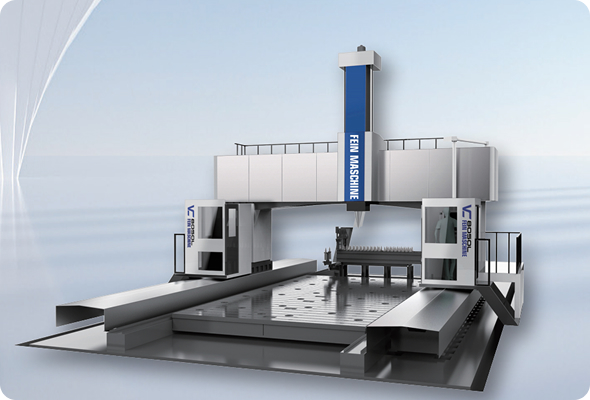
High rigidity | Heavy cutting | High versatility
Integral structure, three-axis composite guide rail with hardened rails, fixed worktable, gantry movement, small floor space, strong load-bearing capacity, and large torque.
Share:
FOR ENGINEERS
PRODUCT INTRODUCTION
Integrated structure, compact and affordable
Integral structure, three-axis composite guide rail with hardened rails, fixed worktable, gantry movement, small floor space, strong load-bearing capacity, and large torque.
The Z-axis is equipped with a 490X320 composite type guide rail and a square slide rest. By replacing the traditional inserts with linear guides, the guiding accuracy is significantly improved, while maintaining the rigidity of the square slide. It is particularly suitable for processing with large cutting volumes and difficult-to-machine materials.
For the Y-axis, our company has developed a proprietary technology for a composite guide rail. Specifically, on the crossbeam, two original linear guides were replaced with one rectangular guide, which increased the cutting resistance moment and the bearing area, significantly enhancing the cutting resistance and effectively overcoming the common weakness of long cutting point cantilevers in gantry machines and large vertical lathes.

The workbench is firmly fixed and has a large load-bearing capacity. Theoretically, there are no restrictions on the working weight. When processing heavy workpieces, it is easy to achieve higher contour accuracy. Moreover, since it is not affected by the weight of the workpiece, its accuracy can be maintained for a long time.
The X direction adopts our proprietary composite guide rail technology. Both the forward and reverse directions use two heavy-duty linear guides and a rectangular guide rail, effectively preventing the overturning force of the gantry during rapid movement and cutting operations.

GMI Integrated 20 and 25 Series Technical Specifications
|
Technical Specs |
unit |
GMI3020 |
GMI4025 |
|
Workbench area |
mm |
3000×1800 |
4000×2300 |
|
Maximum load of the workbench |
t |
30 |
35 |
|
Y1/Y2 travel |
mm |
2000/2500 |
2500/3000 |
|
X/Z Axis Travel |
mm |
3200×1000 |
4200×1000 |
|
Guide rail type |
|
The X-axis is precisely driven on both sides, with each side supported by two linear guides plus a rectangular rail. The Y-axis has dual parallel linear rails supplemented by rigid guide support. The Z-axis uses a hard guide plus double linear rails on the sides for a composite sliding block. |
|
|
Spindle end face to worktable surface |
mm |
200-1200 (customizable) |
|
|
Spindle speed |
rpm |
Standard with BT50-8000, choose 1:4 high-speed gearbox |
|
|
spindle motor |
|
20/25L Series: 22/26 Kw 140/210 Nm (560/840 Nm) | |
|
Tool magazine capacity |
|
24-bit disc |
|
|
Maximum loading width (above the hood) |
mm |
2000 |
2500 |
|
Rapid/Feed Speed |
m/min |
15 / 0-15 |
|
|
Positioning Accuracy / Repeat Positioning Accuracy |
mm |
0.01/0.005 |
|
|
Overall weight |
t |
32 |
37 |
|
Dimensions (excluding electrical cabinet) |
mm |
6700×5200×4200/5200 |
7800×5800×4200/5000 |
|
Typical CNC system configuration |
|
Standard with Siemens 828D and Fanuc 0i MF plus, optional Siemens ONE |
|
A solution for heavy cutting processing of extremely large and extremely heavy wide-width parts
The Z-axis slide ram is equipped with a 500X580 ductile iron square slide ram. After fine grinding and further processed with advanced German injection molding technology, it achieves extremely strong rigidity.
Optional: Equipped with an imported 2500rpm BT50 (or 2000rpm BT60) spindle, which is paired with imported roller bearings and is extremely rigid, capable of withstanding heavy cutting operations. The use of an imported high-performance high-speed reduction gearbox further enables the machine tool to have a cutting torque of 3000Nm.

Square slide rest: 500 × 580 mm

Processing Range Diagram
Hexahedral structure is highly efficient! High precision! Heavy cutting!
The smallest unit for the pentahedral head's segmentation is 5 degrees. It can also be adjusted to 1 degree. The positioning accuracy is 1 second.
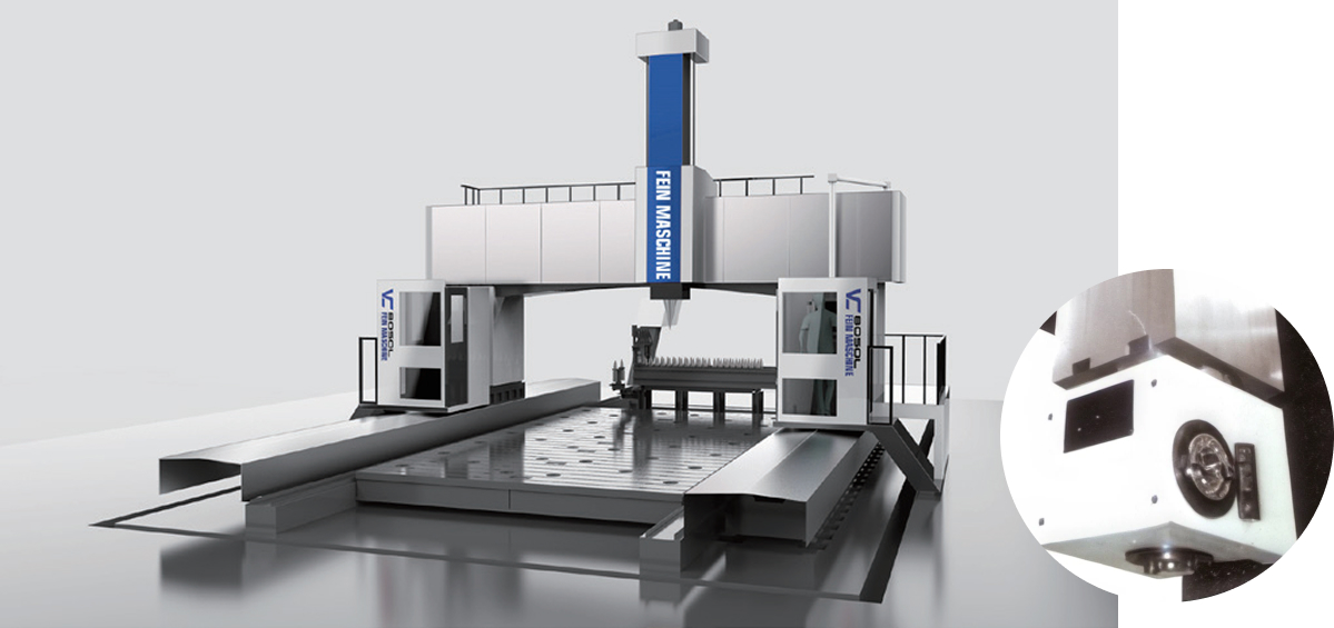
MS Splitter Series 30 and 35
|
Technical Specs |
unit |
GMS60/80- 30 |
GMS60/80- 35 |
GMSXXX35 |
|
|
Workbench area |
mm |
2100×6000/8000 |
2600×6000/8000 |
2600×XXX |
|
|
Maximum load of the workbench |
t/㎡ |
5 |
5 |
5 |
|
|
Y1/Y2 travel |
mm |
3000/3500 |
3500/4000 |
||
|
X/Z Axis Travel |
mm |
6200/8200×1200 |
6200/8200×1200 |
/ |
|
|
Guide rail type |
|
The X-axis isdriven preciselyin bothdirections,with bothsidessupported bytwo linearguides plusa rectangular rail.TheY-axis hasdual linear railssupplemented by hardguidesforstrongvertical support,andtheZ-axis hasasquareslidewitha hardguide. |
|||
|
From spindle end face to worktable surface |
mm |
Standard 350-1550, optional 350-1850 |
|||
|
Spindle drive type |
rpm |
Standard with built-in short direct-connect BT50-6000 dual-speed gearbox (BT50-3000 roller bearing / BT60-2000 roller bearing) / Optional top-mounted long direct-connect with central water outlet |
|||
|
spindle motor |
|
30/35L Series: Standard 37/55.5 kW (rated 1500 rpm) 236/354 Nm (twin-speed gearbox 944/1416 Nm); Optional 28/42 kW (rated 1000 rpm) 268/401 Nm (twin-speed gearbox 1070/1604 Nm) |
|||
|
Tool magazine capacity |
|
24-position rotary/cassette tool magazine |
|||
|
Column spacing |
mm |
3000 |
3500 |
||
|
Rapid/Feed Speed |
m/min |
15 (screw drive) 20 (rack drive) / 0-10 |
|||
|
Positioning Accuracy / Repeat Positioning Accuracy |
mm |
0.01/0.005 |
|||
|
Overall weight |
t |
53/62 |
58/67 |
/ |
|
|
Dimensions (excluding electrical cabinet) |
mm |
11650/13650×6850×5200 |
11650/13650×7750 ×5200 |
/ |
|
|
Typical CNC system configuration |
|
Standard with Siemens 828D, Fanuc 0i MF plus; optional Siemens ONE |
|||
For X direction, when the distance is 6 meters, it is driven by a screw transmission nut for rotation. For distances of 8 meters and above, it adopts a double gear and rack compensation structure.
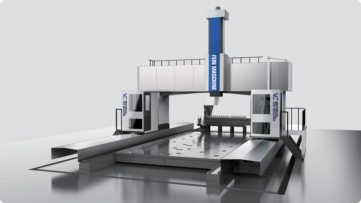
GMS Ultra-wide Series 40, 50, 60 and above
|
Technical Specs |
unit |
GMS60/80- 40 |
GMS60/80- 50 |
GMS80/100- 60 |
GMSXXX50 |
|
Workbench area |
mm |
6000/8000×3100 |
6000/8000×4100 |
8000/10000×5100 |
XXX×4100 |
|
Maximum load of the workbench |
t/㎡ |
5 |
5 |
5 |
5 |
|
Y-axis travel |
mm |
4000/4500 |
5000/5500 |
6000/6500 5000/5500 |
|
|
X/Z Axis Travel |
mm |
6200/8200 ×1200 |
6200/8200×1200 |
8200/10200×1200 |
/ |
|
Guide rail type |
|
The X-axis is driven precisely in both directions, with both sides supported by two linear guides plus a rectangular rail. The Y-axis has dual linear rails supplemented by hard rails for strong vertical support. The Z-axis has a square sliding carriage with hard rails. |
|||
|
Spindle end face to worktable surface |
mm |
Standard 350-1550, optional 350-1850 |
|||
|
Spindle drive type |
rpm |
Standard with built-in short direct-connect BT50-6000 dual-speed gearbox (BT50-3000 roller bearing / BT60-2000 roller bearing) / Optional to long direct-connect with central water outlet |
|||
|
spindle motor |
|
30/35L Series: Standard 37/55.5 kW (rated 1500 rpm) 236/354 Nm (twin-speed gearbox 944/1416 Nm); Optional 28/42 kW (rated 1000 rpm) 268/401 Nm (twin-speed gearbox 1070/1604 Nm) |
|||
|
Tool magazine capacity |
|
24-position rotary disk / warehouse-style tool magazine |
|||
|
Column spacing |
mm |
4000 |
5000 |
6000 |
5000 |
|
Rapid/Feed Speed |
m/min |
15 / 0-10 |
|||
|
Positioning Accuracy / Repeat Positioning Accuracy |
mm |
0.01/0.005 |
|||
|
Overall weight |
t |
62/72 |
69/79 |
84/95 |
/ |
|
Dimensions (excluding electrical cabinet) |
mm |
11650/13650×7350×5200 |
11650/13650×8350×5200 |
13650/15650×9350×5200 |
/ |
|
Typical CNC system configuration |
|
Standard with Siemens 828D, Fanuc 0i MF plus; optional Siemens ONE |
|||
For the Y-axis of 6 meters and above, a double-gear rack and pinion backlash elimination structure is adopted.
For the ultra-wide series of models, the length of the worktable and the Y-axis travel increase by 1 meter each, and the model will be changed accordingly.
Gantry cranes of 6 meters and above use rack and pinion rotation and a synchronous dual-drive four-motor, same-direction differential backlash-free motion structure.

The gear rack is made using high-precision, large-module grinding, resulting in high strength and high precision.

Synchronous dual-drive four-motor synchronized differential offset motion in the same direction.
FOR PROCUREMENT
FOR QUALITY
01
Finite Element Analysis
The machine tool design was carried out in cooperation with renowned domestic universities, and internationally advanced finite element analysis was adopted to ensure that the dynamic and static characteristics of the machine tool are reasonable, the load is reasonable, and the load distribution is uniform.

02
Collimator
The machine tool design was carried out in cooperation with renowned domestic universities, and internationally advanced finite element analysis was adopted to ensure that the dynamic and static characteristics of the machine tool are reasonable, the load is reasonable, and the load distribution is uniform.

03
Vibration meter
The machine tool design was carried out in cooperation with renowned domestic universities, and internationally advanced finite element analysis was adopted to ensure that the dynamic and static characteristics of the machine tool are reasonable, the load is reasonable, and the load distribution is uniform.

04
Bar ballinspection
Each machine is equipped with a ball gauge from RENISHAW of the UK. It is used to calibrate the true circularity and the geometric accuracy of the machine, and at the same time, circular cutting experiments are conducted to ensure the 3D processing accuracy and circular accuracy of the machine.

05
Three axes laser inspection
Each machine of Ningqing is calibrated using the laser interferometer from RENISHAW Company in the UK. Precise inspections and compensations are carried out for pitch errors, backlash, positioning accuracy, and repeatability positioning accuracy, etc., to ensure the dynamic, static stability and processing accuracy of the machines.

06
Three-coordinate system
We have established a comprehensive quality control system covering the entire chain from raw material warehousing and processing to finished product delivery. Using a coordinate measuring machine (CMM) as the core inspection tool, we conduct dimensional and geometric tolerance checks on key components. At the final product delivery stage, each machine tool must undergo standard test piece processing and testing, and an S-piece test is performed to verify dynamic accuracy and contour deviation using universal standards. The CMM is integrated throughout the entire product lifecycle, forming a closed-loop manufacturing process of "inspection-feedback-compensation," ensuring that every CNC machine tool leaving the factory possesses verifiable accuracy.



High Quality 5-Axis CNC Machine | Self-developed by Fein brand
Premium beam mobile 5-axis machines made with aerospace reliability. Competitive factory price, OEM/ODM accepted. Get free quote for your industrial workshop today.